Diy Arduino Vacuum Cleaner

Sign up or log in to customize your list.Build Yourself a Sophisticated, 3D Printed Robot VacuumHigh on the list of thankless household tasks like mowing the lawn, doing the dishes, and taking care of laundry chores is vacuuming floors. The monotonous and time-consuming activity of sucking up all the nasty detritus that collects on floors has inspired products like the Roomba, a not-very-inexpensive solution to the problem.Enter Jake Lee.Lee is a product and industrial designer from Taiwan, and at age 36, he’s about to welcome the birth of a son, hence the name of his cleaning robot project. Lee says his son’s nickname, “Panda,” provided him a ready name for this interesting, 3D printed vacuum project, Panda – The Ultimate Cleaning Robot.He says it’s an an improved version of a previous attempt he made at designing and building a cleaning robot, and this one features more robust construction, air suction, a sweeper, and roller brush.The robot is able to randomly select a direction to move, and then it’s capable of detecting obstacles and sudden dropoffs.

And don’t think taking on this project is a weekend chore as it required Lee nearly a full month to draft the mechanical layout, plan the electrical system, and square away the software.A couple of years ago, Lee had built a previous attempt, but due to its very small footprint and the requirement to have a connected power source such as PC to make it run, he wanted to take another shot at building something more autonomous.
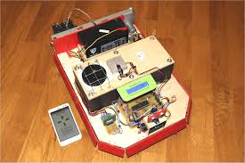
Wedding Dress Prices KleinfeldsThis latest version features a list of 3D printed parts such as a top and bottom housing, a mid housing, a pair of battery covers, a gear box cover, and a dust chamber.
Wedding Dress Shop Sandy BedfordshireAdd in a couple of 135 RPM gear motors to drive the wheels, a 1000 RPM motor to drive the roller and sweeper, a DC 3V motor for the vacuuming tasks and driving the fan blade, and an UNO board and eight batteries, and you have a rather complex device indeed.
Jeep Jk Military Seat Covers
Lee says he designed the robot to fit within the dimensions of his MakerBot’s build area and used PRO_E to take on the 3D modeling tasks.He says that it took “an enormous amount of time to complete this project” but adds that he was pleased with the result. You can check out his highly detailed Instructable here.Will you try building your own 3D printed robot vacuum cleaning following Jake Lee’s design? Tagged with: 3d printed products • 3d printed vacuum • 3d printed vacuum cleaner • instructables • vacuum cleaner Does this project spark your interest? Become a member to follow this project and don't miss any updates Fancy lathe made from garbage A wood lathe with closed loop speed control made from garbage The title says it. I'm making a wood lathe primarily from garbage and dollar store items. because that's what I do here. What makes it fancy? Well, that's relative to the usual DIY lathe projects I see. There are many of them out there, and they are typically a hand drill or a motor with a switch attached to a board.

Some of them look beautiful and work really well, but mine will be a tad different.The main feature that makes this project different is that it will have closed loop speed control. With a lathe, speed control is pretty important, but I'm certainly not going to put together a complicated gear set to achieve it. I'm going to take a stab at controlling the speed electronically. Here is a quick overview of the project. All of the details will be added in the project logs.Attempt 1 of 2 (unsuccessful):- 100V 1kW universal motor from a vacuum cleaner.- high power rectifier and IGBT set from an inverter type microwave oven.- ATmega 328 controller - structure made from 2x4 and other scrap lumber- reflectance sensor attached to motor for tachometer- LCD display on the control panel- Here's the schematic (or click the one on the left for larger version)Attempt 2 of 2(also unsuccessful):- AC motor from washing machine- Triac pair (BCR8PM) and accompanying circuitry from washing machine- MOC3063 triac drivers- other parts from attempt 1Here's the schematic:
A much simpler way of doing it I tried something different. As much as I like the idea of the speed control, I decided to just make something that works. If I like the hobby enough, I'll probably just buy a commercial lathe. I'm still building my own.This new version is very different and lacks the defining feature of this project(electronic speed control), so I wrote it up as a separate project here: https://hackaday.io/project/7408-a-simpler-cheaper-latheEnjoy. I told you I had never worked with AC motors. Cut me some slack.I built the circuitry and tested it out. The controller doesn't use regular PWM. Rather it switches on full 60Hz cycles. Thanks to the MOC3063 drivers this switching occurs at zero crossings. For example a half power setting would switch on every other cycle.Things seemed to work ok. But I noticed that at low power the motor was not so smooth and something just seemed wrong, so I did a little more research. I guess the motor was designed to spin at one particular speed and the right way to control the speed is by changing the AC frequency.

It's not an impossible challenge, but I'm currently lacking the free time and motivation to delve into it. I also considered just building the thing with a one speed motor, but that kind of defeats the mission statement of the project.Plus, the more I learn about wood lathes the more tempted I am to actually buy a proper one and try my hand at wood turning. Of course I would like to try my hand a few times before investing the large sum of money, so I'm keeping my eyes open for such an opportunity. New motor, time to redesign After a few nervous tests with some wood, I've decided that this motor just isn't a good choice. As you pointed out in the comments, vacuum motors are designed for high speed and low torque, which is just the opposite of what I need. I thought I could get away with it if I made a nice controller, but I changed my mind and set out in search of a better motor.I was fortunate enough to get my hands on this very clean washing machine motor and accompanying circuitry.

But with this new gem that is designed for low speed and high torque I will make another attempt at a wood lathe. Unfortunately, since this is an AC brushless motor, I will have to completely redesign my driver circuit. I am planning to use the triacs from the washing machine along with some MOC3043 chips to drive them. I'm still doing my homework to figure out a good design since I've never driven AC motors before.In addition to that, I will have to redesign the whole interface between the motor and wood. I salvaged the other pulley and belt as well, so I will probably make use of them. I'll post again when I have a working design. Mechanical bits and a control panel I spent some time working out the more lathey parts. By that I mean the structure and spur centers. It would be easiest to just show you what I did.This is the moveable center that slides along a 2x4 and can be clamped in place:The circular knob was cut with a jigsaw using a hackaday SPACE coaster as a template.
Did you know that those coasters are exactly as wide as a 2x4? I'm pretty sure that was a coincidence. This picture shows how I attached a 6mm threaded rod.Next was the live center which consists of a long 6mm nut that I modified with a cutoff wheel on an angle grinder.Here the two centers are facing each other.Oh, and I sharpened the threaded rod too.Next, I finally made a control panel out of a plastic cutting board that I had left over from the stargate project. It just has a power switch, rotary encoder knob and a display. I was thinking of putting start and stop buttons on there too, but haven't gotten my hands on any good buttons for the job. At this point I can just use the knob and start out at 0 rpm. The power switch is my quick shut off.Here is the back side of the control panel. Notice that the knob is still attached to a chunk of pcb from the stereo I pulled it out of. Everything is held together with hot glue. Rough assembly and some tests The motor is now attached to a 2x4 using some wood blocks and L brackets as you can see in the pictures.
It feels really solid. Right behind the motor is the control box, which is a plastic food container from the 100 yen store. It is still far from complete, but functional. It will eventually have a control panel on the top, but at this point the controls and display are just hanging over the edge.As for the tests, I first programmed it with some really basic debugging code and connected it to a small light bulb instead of the motor. It worked ok, but the bulb didn't seem to respond to the changes in pwm duty cycle as much as expected. Anyway, I finally got up the confidence to connect the motor and ZOOM! The IGBT failed in such a way that it was stuck on. The motor screamed like a jet engine for three seconds till I yanked the plug from the socket.I'm not sure, but some reading seems to suggest over voltage from the inductive load. I thought my flyback diodes would protect things, but maybe not. Also, the unresponsiveness to the duty cycle made me wonder if my IGBT driving was not good enough.